European construction equipment OEMs are increasingly specifying excavator bucket teeth with integrated wear indicators as a critical component of their predictive maintenance programs. These indicators—precisely machined grooves or steps at a calibrated depth on the tooth profile—give maintenance crews a quick visual check: once the indicator disappears, the tooth has reached its service limit and must be replaced before wear reaches the adapter. For OEMs building service contracts around uptime guarantees and scheduled maintenance intervals, a bucket tooth that communicates its own remaining life eliminates guesswork and prevents the cascade of damage that follows from a worn tooth chewing into the adapter nose. At JM China (Ningbo Yinzhou Join Machinery Co., Ltd.), we have manufactured excavator bucket teeth with wear indicators for over sixteen years, supplying European OEM supply chains with precision-cast ground engaging tools designed to integrate seamlessly into predictive maintenance workflows.
Our facility in Ningbo produces bucket teeth ranging from 0.1 kg mini-digger points to 150+ kg heavy mining teeth across seven dedicated production departments. With 150 employees, an in-house R&D team, and fifteen finished-product inspectors, we control every variable that matters to an OEM procurement engineer: dimensional accuracy, material chemistry, heat treat consistency, and the precise placement of that wear indicator groove that makes predictive maintenance possible.
Why European OEMs Demand Wear Indicators on Excavator Bucket Teeth
The economics of unplanned downtime in European construction are unforgiving. A single excavator sitting idle on a German Autobahn widening project or a French quarry operation costs between €500 and €1,500 per hour in lost production, labor waiting time, and penalty clauses. When a bucket tooth wears past its safe limit without detection, the damage travels up the assembly: the tooth tip snaps, the adapter nose wears asymmetrically, the bucket edge distorts, and a €15 replacement tooth becomes a €400 repair job involving welding, grinding, and liner replacement.
European OEMs have responded by embedding predictive maintenance into their service agreements. Instead of calendar-based replacement schedules that waste partially worn teeth or run past safe limits, they now rely on condition-based triggers. The wear indicator groove on a bucket tooth provides exactly that trigger: a physical, inspectable threshold that requires no electronics, no telematics module, and no specialized training to read.
Our engineers have observed that European fleet managers typically inspect wear indicators during the daily walkaround—the same five-minute check that covers fluid levels, track tension, and hydraulic hoses. A foreman or operator glances at the tooth face; if the indicator groove is still visible, the tooth stays in service. If the groove has worn flush or disappeared, the tooth goes on the replacement list for the next maintenance window. Simple, repeatable, reliable.
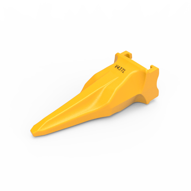
How Wear Indicator Grooves Are Designed and Machined
A wear indicator on a bucket tooth is not an afterthought. It is a deliberate geometric feature calculated from the tooth’s wear profile, material hardness, and expected service life. We machine the indicator groove at a depth that corresponds to approximately 60-70% of the tooth’s useful material volume. At this point, the tooth still has enough structural meat to complete its current shift safely, but the operator can schedule replacement before the tooth wears into the adapter seating area.
The groove geometry matters. Shallow V-grooves become invisible too early and trigger premature replacement. Deep grooves risk creating a stress riser that initiates cracking. We have settled on a radiused-bottom groove between 4 mm and 8 mm deep depending on tooth size and application, verified by CMM inspection on every production die set. Our technical director, who previously led product development for BYG ground engaging tools, oversaw the refinement of these groove profiles across multiple tooth families.
For OEM customers who define their own service intervals, we adjust the indicator depth accordingly. A quarry operator running teeth against granite wants a deeper reserve than a utility contractor digging in sandy loam. We maintain dimensioned drawings for each indicator variant and keep the corresponding die inserts on file for repeat orders.
Material Selection and Heat Treatment for Predictable Wear
A wear indicator is only useful if the tooth itself wears predictably. If hardness varies across the tooth profile, the indicator groove will erode unevenly and provide a false reading. That is why our material and heat treat specifications are engineered for uniform wear front to back.
We cast our bucket teeth from high-carbon alloy steel grades selected for the specific application: through-hardened grades for general construction, impact-resistant alloys for demolition and ripping work. Each melt is sampled and analyzed by optical emission spectrometer before pouring. The chemistry must hit tight ranges for carbon (0.30-0.45%), manganese, chromium, and molybdenum—elements that control depth of hardening and abrasion resistance.
The heat treatment sequence is equally critical. We austenitize at controlled temperatures, quench in polymer quenchant (not water, which creates uneven cooling), and temper in two separate cycles to relieve internal stresses. Target hardness for our standard construction-grade teeth is 48-52 HRC at the wear surface, measured at three positions along the tooth profile. Batch-level Brinell hardness testing is documented and retained per our ISO 9001:2015 procedures. For customers who require third-party verification, we arrange independent testing at a NABL-accredited lab in Shanghai.
The result is a tooth that loses material at a consistent rate across its working face. The indicator groove wears evenly and predictably, which means the visual trigger corresponds to a real, repeatable remaining-life estimate—not a guess.
Integration with European OEM Telematics and Fleet Management Systems
While the wear indicator itself is a purely mechanical feature, European OEMs are increasingly connecting visual wear data to their digital fleet management platforms. We see this trend accelerating across Caterpillar’s VisionLink, Volvo’s CareTrack, and Komatsu’s Komtrax systems. The process works as follows: during the daily walkaround, the operator or service technician records the wear status of each tooth position—indicator visible, partially worn, or gone—using a mobile app or in-cab tablet. The fleet management system aggregates this data across all machines on site and generates a prioritized replacement schedule.
This hybrid approach—physical indicator at the component level, digital tracking at the fleet level—gives the OEM and the end customer a double layer of protection. The visual indicator catches edge cases that sensor-only systems miss (damaged teeth, impact fractures, uneven loading), while the telematics layer catches what human inspection might overlook (trends across multiple machines, correlation with operating hours, predictive wear curves).
We support this workflow by manufacturing teeth that fit standard adapter interfaces across the major European excavator brands. Our Caterpillar J400-series replacement tooth, for example, matches the pin center distance, adapter angle, and seating profile of the OE component while adding the wear indicator groove that the OEM’s predictive maintenance program requires. Similarly, our Volvo VOE11417129-compatible standard tip point and Komatsu 195-78-21331 ripper tooth all carry our standard wear indicator.
Production Quality Control That OEM Auditors Can Verify
European OEMs do not take quality claims at face value. Their supplier quality engineers visit our plant, audit our processes, and review our documentation. We have structured our QC system around five inspection gates that a visiting auditor can walk through and verify independently.
Gate one—raw material: Every incoming heat of steel is accompanied by a mill certificate and verified by our spectrometer. Rejected chemistries are segregated and returned to the mill. We maintain a material traceability log that links each heat number to the production orders it supplied.
Gate two—casting: Shell molds are inspected for crack defects and dimensional trueness before pouring. First-article castings from each die set are measured on a coordinate measuring machine against the 3D model. Deviations beyond ±0.5 mm on critical dimensions (seating face, pin bore, indicator depth) trigger die rework.
Gate three—heat treatment: Load thermocouples in every furnace run verify temperature uniformity. Hardness coupons from each load are Brinell-tested. If a single coupon falls outside the specified range, the entire load is re-sorted and re-tested. Records are signed off by both the heat treat operator and the QC supervisor.
Gate four—finished product: Each tooth passes through a magnetic particle inspection station for crack detection. Indicators are gauged for depth and profile. Fifteen inspectors work on this gate alone, each one assigned to a specific inspection parameter with documented pass-fail criteria.
Gate five—packing and shipping: Before sealing, our packing team performs a final visual check. Any tooth with a casting defect, incomplete indicator groove, or dimensional deviation is pulled and sent to the rework or scrap bin. We do not blend non-conforming product into orders.
This is the system we have run since 2006, and it is the system that has kept our customers—including companies that supply BYG, JCB, and NBLF—coming back. It is also the system that European OEM sourcing teams verify during their annual supplier audits, and we pass each time.
The Cost Case: Why OEMs Switch to Wear-Indicator Teeth
The purchasing decision for a European OEM procurement team comes down to total cost of ownership across the service contract, not unit price per tooth. We have seen the arithmetic play out repeatedly: a standard bucket tooth without a wear indicator costs the OEM roughly the same as a tooth with an indicator, within a few percent. But the downstream costs differ significantly.
Without a wear indicator, the end customer either replaces teeth too early (wasting 20-30% of usable service life) or too late (damaging adapters and buckets). In the first case, the OEM subsidizes premature replacement under the service contract. In the second case, the OEM covers warranty repairs that could have been prevented. Both scenarios erode the margin on what is already a low-margin components business.
With a wear indicator, the end customer replaces teeth at exactly the right point—when the indicator signals that the tooth has delivered its full service value but the adapter is still protected. The OEM’s service costs become predictable. Replacement intervals can be modeled, budgeted, and optimized. This is why we see European OEM specification documents now explicitly require wear indicators on bucket teeth for machines covered under predictive maintenance service agreements.
Custom Development for OEM-Specific Wear Indicator Specifications
We regularly work with European OEM engineering teams to develop custom wear indicator configurations. The process typically starts with the OEM sharing their target service life for a given tooth size and application—for example, 800 operating hours in mixed soil conditions on a 30-ton excavator. Our engineering team runs the tooth geometry and material properties through a wear model to determine the optimal indicator depth, then machines a prototype die insert and produces a sample lot.
The OEM tests the samples on their own machines or at customer sites, measuring actual wear rates against the projected indicator life. We adjust the indicator depth based on the field data and lock the final specification into our die set. The entire cycle—from first design meeting to production-ready die insert—typically takes 8 to 12 weeks for a new tooth profile, faster if the tooth shares an existing adapter interface.
One European OEM we supply recently asked us to move the indicator groove 2 mm deeper on a specific tooth model after their field tests showed that their customers’ operators were not inspecting teeth frequently enough to catch the original trigger point. We modified the die insert within two weeks and delivered the updated tooth on the next production run. That is the level of responsiveness that a vertically integrated foundry can provide—something an offshore trading company cannot match.
How to Evaluate a Bucket Tooth Supplier for EU OEM Requirements
If your sourcing or engineering team is evaluating bucket tooth suppliers for integration into European OEM predictive maintenance programs, we suggest a structured qualification process:
- Request dimensional reports for indicator depth, seating face flatness, and pin bore position on the tooth family you need. Cross-reference these against your own mating adapter measurements.
- Audit the heat treat process in person or via video walkthrough. Look for load thermocouples, documented quench parameters, and hardness records linked to specific batch numbers.
- Verify material chemistry against your specification. Ask for spectrometer reports for three consecutive production runs, not just one cherry-picked result.
- Test the indicator visual detection yourself. Place sample teeth at eye level in the lighting conditions your operators will work in, and confirm the indicator groove is clearly visible at the intended wear point.
- Review the supplier quality system documentation, including ISO 9001:2015 certificates, inspection procedures, and non-conformance tracking records.
We make these documents available to all prospective OEM customers during the evaluation phase. Our plant in Ningbo is open for supplier audits by appointment, and we have hosted visiting engineers from European OEMs at our facility every year since our founding in 2006.
Parting Perspective: The Shift Is Already Underway
The European construction equipment market is moving toward outcome-based service models—the OEM gets paid for machine uptime, not parts sales. This shift makes every component that contributes to predictable maintenance scheduling strategically important. Excavator bucket teeth with wear indicators are a small but telling example of this trend. They represent a component-level solution to a system-level problem: how to keep a fleet of excavators running without unnecessary downtime or premature part replacement.
We manufacture excavator bucket teeth with wear indicators for European OEMs that take this approach seriously. Our teeth are cast from controlled-chemistry alloy steel, through-hardened for uniform wear, and fitted with indicator grooves that give maintenance teams a reliable visual trigger for replacement. We also supply complementary G.E.T. components—cutting edges, adapters, pins, retainers, bolts, and nuts—from the same vertically integrated production system. If your OEM procurement team is specifying wear-indicator teeth for your next generation of predictive maintenance service agreements, contact our export team with your dimensional requirements and target service intervals. We will send you samples, dimensional reports, and a production timeline within two weeks of receiving your inquiry.
Frequently Asked Questions
Xin Jack — Export Sales Manager at Ningbo Yinzhou Join Machinery Co., Ltd. Xin Jack is the Export Sales Manager at Ningbo Yinzhou Join Machinery Co., Ltd., a specialized manufacturer of G.E.T. (Ground Engaging Tools) parts including bucket teeth, cutting edges, and adapters for excavators and construction equipment. Established in 2006, the company serves European and American markets with 16 years of exporting experience, partnering with world-leading brands such as BYG, JCB, and NBLF. Every product undergoes strict quality control from raw material to finished goods, ensuring maximum cost performance for global construction and mining customers.
Post time: Jun-25-2026